

Self-Test GFCI Outlets Explained: Test, Reset, and Indicator Lights

Quick answer
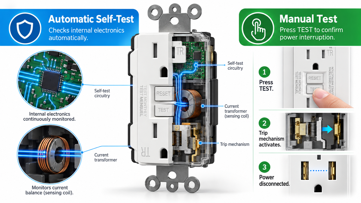
A self-test GFCI automatically checks much of its internal sensing electronics, but it does not replace the face-button test. The Test button makes the device trip so its mechanical switching path is exercised. Reset attempts to restore power after the test or fault condition has cleared. The indicator light reports a status defined by the manufacturer, so its color or blink pattern must be read from the instructions for that exact model.
UL 943 began requiring auto-monitoring on covered GFCI receptacles and circuit breakers manufactured to the revised standard as of June 29, 2015.[1] UL explains that the internal monitor checks the electronic path from the sensing toroid up to the trip-solenoid driver, while the driver itself, the solenoid, and welded contacts can be verified only by causing a real trip.[1] That division of labor is why the manual button remains important.
The key points:
- Test proves that power can be interrupted. If pressing Test leaves the receptacle energized, stop relying on its GFCI protection.
- Reset is a restoration control. It may not latch when line power is absent, a fault remains, line/load wiring is wrong, or the device has reached a failure state.
- Indicator colors are model-specific. Green, red, amber, steady, and flashing do not have one universal meaning across all GFCI products.
- Auto-monitoring has a defined boundary. It detects many internal electronic failures but cannot prove that the solenoid and contacts will physically open.[1]
- The standard and the product can use different schedules. The UL 943 requirement is commonly summarized as a self-check at least every three hours; ELEGRP states that its standard GFCI runs one every five seconds.[3][4]
- Troubleshooting stays safety-first. Water inside the box, scorching, repeated trips with all loads removed, or uncertain line/load wiring belongs with a licensed electrician.
Read Test, Reset, and the indicator as three separate signals
The controls sit close together, but they answer different questions. Start with what you can observe and take the matching action.
| What you observe | What it tells you | What to do next |
|---|---|---|
| Pressing Test cuts power | The device completed a manual trip at that moment | Press Reset, confirm power returns, and keep testing on the schedule in the instructions |
| Pressing Test does not cut power | The manual trip did not produce the required result | Stop using the receptacle as protected; replace it or call a licensed electrician |
| Reset restores power after a successful test | The device can relatch after the test condition clears | Confirm the receptacle and known downstream outlets are energized again |
| Reset will not latch | The device may lack line power, still see a fault, be miswired, or have failed | Unplug loads, check upstream power, then follow the troubleshooting sequence below |
| Indicator changes color or flashes | The device is reporting a model-specific state | Read the face label and exact manufacturer's instructions before interpreting it |
| Indicator looks normal but Test fails | The light does not override the failed manual result | Stop relying on the device and arrange replacement |
A plug-in lamp or receptacle tester can confirm whether power went off and returned. It cannot certify the internal trip threshold or replace the listed test procedure. Follow the instructions supplied with the installed model, especially if it is a breaker, portable GFCI, dual-function device, or receptacle with a different reset sequence.
What the automatic self-test checks
A Class A GFCI compares current leaving on the ungrounded conductor with current returning on the grounded conductor. UL describes the residential Class A operating band as no trip below 4 mA and a required trip at 6 mA or more.[2] That sensitivity is intended to reduce shock risk; it is different from the much higher current at which a branch-circuit breaker responds to overload.
The auto-monitoring circuit creates an internal test signal and checks much of the electronic detection path. UL's explanation places that monitored path from the sensing toroid to the trip-solenoid driver, then explicitly says the driver, trip solenoid, and contacts cannot be tested by the monitor.[1] Only a trip can show that those components physically operate.
| Protective function | Automatic monitor | Manual Test button |
|---|---|---|
| Checks much of the sensing and control electronics | Yes, on the device's programmed schedule | Also involved when a test signal is created |
| Proves the trip-solenoid driver can actuate the mechanism | No | Yes, as part of a successful trip |
| Proves the trip solenoid moves | No | Yes, as part of a successful trip |
| Proves the contacts are not welded closed | No | Yes, because power must actually open |
| Requires the user to be present | No | Yes |
UL 943 generally requires power denial when the auto-monitor detects a test failure or the GFCI reaches end of life. UL also describes narrow exceptions for an open trip solenoid or open driver component, where an audible or visual indication may be allowed because the device can no longer trip itself open.[1] This standard-level rule does not create a universal LED code; the product instructions still decide what a particular signal means.

UL's minimum schedule and ELEGRP's five-second implementation
The schedule needs precise wording because two correct numbers describe different things. Industry coverage of the revised UL 943 requirement states that the automatic test occurs when line/load power is applied and then at least once every three hours for the life of the device.[3] That is the standards baseline for covered products, not a claim that every design waits exactly three hours.
ELEGRP publishes a shorter interval for its standard GFCI receptacle: an automatic self-test every five seconds.[4] The product page also lists twin solenoids, dual silicon-controlled rectifiers, tamper-resistant shutters, more than 6,000 factory tests, 15 A and 20 A options, and UL/cUL listing.[4]
| Question | UL 943 baseline | ELEGRP standard GFCI |
|---|---|---|
| Is auto-monitoring required? | Yes, for covered devices manufactured to the revised requirement from June 29, 2015[1] | Yes; the product page describes patented self-testing[4] |
| How often is the electronic check run? | At power application and at least every three hours, as summarized in industry coverage[3] | Every five seconds, according to ELEGRP[4] |
| Does it replace the face-button test? | No; UL says the manual button should still be used periodically[1] | No; follow the product's Test instructions |
A faster automatic interval increases how often the electronic path is checked. It does not expand the monitor into the mechanical components that only a manual trip can exercise. Keep frequency and coverage as separate specifications.
How to run a manual GFCI test
Follow the label and instructions for the exact device. For a typical receptacle-style GFCI, the sequence is:
- Make the test safe for connected equipment. Save work and unplug sensitive loads from the receptacle and any downstream outlets you know it protects.
- Confirm line power is present. A lamp or tester should show that the receptacle is energized before the test begins.
- Press the Test button. The button should trip the device, and power should switch off at the receptacle.
- Verify the protected points are dead. Check the GFCI face and known load-side receptacles with the same lamp or tester.
- Press Reset as directed. The button should latch and restore power after a successful test.
- Confirm restoration. Recheck the receptacle and the same known downstream points.
Many receptacle faces are marked “TEST MONTHLY.” Use the interval printed on the installed device or stated in its instructions. UL's published explanation says the manual button should still be used periodically because auto-monitoring cannot test the solenoid, driver, or contacts.[1]
A failed result takes priority over the indicator light. If Test does not interrupt power, do not keep repeating the procedure or assume the LED proves protection. Remove the receptacle from service as a protected point and arrange replacement. If you must remove or replace the device, turn off the breaker and verify that the box is de-energized; uncertain line/load identification should be handled by a licensed electrician.
How to interpret the indicator light safely
There is no cross-brand rule that assigns one meaning to every color and blink pattern. One model may use green for normal operation; another may use green to show power only. Red can indicate a trip, reversed wiring, failed self-test, or end of life depending on the product. Some devices illuminate only during a fault, while others maintain a status light continuously.
Use this order:
- Read the markings on the device face. A short legend may be molded or printed beside the indicator.
- Identify the exact model. Amperage, weather resistance, nightlight, USB, and portable variants can use different signal logic even within one brand.
- Find that model's instructions. Match the observed color, steady/flash state, power state, and button behavior to the manufacturer's table.
- Run the prescribed manual test when safe. A light that appears normal cannot compensate for a Test button that fails to interrupt power.
- Replace an end-of-life device. A status defined as failed self-test or end of life is not cleared by repeated resets.
Do not infer that every energized receptacle with a light has suffered one of UL's narrow solenoid exceptions. The standard allows certain response paths, while the manufacturer assigns the visible indication for its design. Observation plus model instructions provides the reliable interpretation.
What to do when Reset will not stay in
A Reset button that will not latch has several possible causes, so troubleshoot from the supply side toward the device.
First, confirm upstream power. Check the branch-circuit breaker and any upstream GFCI that may feed this receptacle. A receptacle cannot reset if no line power reaches it, and a downstream outlet may be protected by a GFCI located in another bathroom, garage, basement, or exterior area.
Second, remove connected loads. Unplug everything from the GFCI and known downstream receptacles, then try the manufacturer's reset procedure once. If it latches, reconnect loads individually. A trip associated with one appliance points to that appliance or cord rather than the receptacle face.
Third, stop if water or damage is involved. Do not energize a box that may contain water. Scorching, melted plastic, a hot faceplate, corrosion, or repeated tripping with all loads removed also calls for a licensed electrician. Drying a countertop does not establish that the inside of the box is safe.
Fourth, consider wiring and end of life. Reversed line/load conductors, a downstream fault, a damaged cable, or a failed GFCI can all prevent restoration. UL 943 includes miswiring and power-denial provisions, but the exact reset behavior varies by design.[1] Line-voltage diagnosis requires the circuit to be switched off and verified dead.

What the 2015 date does—and does not—tell you
June 29, 2015 is the effective manufacturing date in UL's explanation of the revised auto-monitoring requirement.[1] It applies to GFCI receptacles and circuit breakers covered by that UL 943 requirement. It should not be rewritten as a global statement that every device sold everywhere after that day has identical behavior.
Older listed devices could remain in distribution after the effective date, and installed receptacles can stay in service for years. If the age or self-test capability is uncertain, identify the model from the face and yoke markings or replace it with a current listed device. Whatever its age, a GFCI that fails the manual test should not be relied on for shock protection.
AFCI vs GFCI: keep the hazards separate
The short AFCI vs GFCI distinction is hazard-based. A GFCI receptacle detects current leaving its intended path and is used for shock protection. An AFCI detects signatures associated with electrical arcing and is used to reduce fire risk in branch-circuit wiring. A location or circuit can require one or both; neither function automatically substitutes for the other.
Requirements depend on the locally adopted National Electrical Code edition and amendments. The authority having jurisdiction determines what applies to a specific installation. For a full room-by-room treatment, use the dedicated guide to where GFCI protection is required; this article stays focused on testing and interpreting an installed device.
When replacement is appropriate, ELEGRP's standard GFCI keeps the user-facing routine simple: Test and Reset on the face, a status indicator, and a self-test that the manufacturer says runs every five seconds.[4] Its 1.5 × 1.68 × 2.7-inch body is offered in 15 A and 20 A versions with a screwless plate included, tamper-resistant shutters, and UL/cUL listing.[4] ELEGRP's GFCI range at store.elegrp.com also includes weather-resistant, USB-C, nightlight, and portable formats. Match the format to the location, then follow the exact model's indicator and reset instructions.
Frequently asked questions
Does a self-test GFCI replace manual testing?
No. UL says auto-monitoring checks much of the electronics from the sensing toroid to the trip-solenoid driver, but it cannot test the driver itself, the trip solenoid, or welded contacts.[1] Pressing the Test button causes a trip and verifies that the switching path actually interrupts power.
How often should I press the Test button?
Follow the interval printed on the device and stated in its instructions; many GFCI receptacles are marked “TEST MONTHLY.” UL's explanation says the button should still be used periodically on self-testing models.[1] The automatic five-second or three-hour electronic interval is a separate schedule and does not replace the user's test.
What should happen when I press Test?
Power should switch off at the GFCI receptacle and at outlets connected to its load side. Verify with a lamp or tester, then press Reset according to the manufacturer's procedure and confirm that power returns. If Test leaves the receptacle energized, stop relying on its GFCI protection and arrange replacement.
Why will the Reset button not stay in?
The receptacle may have no upstream power, still detect a connected or downstream fault, contain moisture or damage, have reversed line/load wiring, or have reached a failure state. Check the breaker and upstream GFCIs, unplug loads, and try the specified reset procedure once. Water inside the box, damage, or repeated failure with loads removed requires a licensed electrician.
What does a red or blinking GFCI light mean?
The meaning is model-specific. Read the face legend and instructions for the exact GFCI before assigning a meaning to any color or flash pattern. Combine the light state with whether power is present and whether the Test button successfully interrupts it. A failed manual test overrides a normal-looking indicator.
When did self-test become required for GFCI receptacles?
UL's published explanation gives June 29, 2015 as the effective date when covered GFCI receptacles and circuit breakers manufactured to the revised UL 943 requirement needed auto-monitoring.[1] Older listed stock could remain in commerce, so a purchase or installation date alone may not establish the manufacturing standard.
What is the difference between AFCI and GFCI protection?
GFCI protection addresses shock by detecting current leaving the intended circuit path. AFCI protection addresses fire risk by detecting electrical arcing signatures. A circuit may require both under the locally adopted code. The two functions respond to different hazards and are not interchangeable.
The bottom line
Treat Test, Reset, and the indicator as three separate signals. Test proves that the device can interrupt power, Reset attempts to restore power after the condition clears, and the light communicates a status defined by the exact model.
Self-test adds frequent electronic monitoring, but its coverage has a physical limit. The practical routine is therefore unchanged: follow the device's manual-test schedule, verify that power actually goes off and returns, consult the exact indicator legend, and stop when water, damage, failed testing, or uncertain wiring makes the result unsafe to diagnose at the face.


